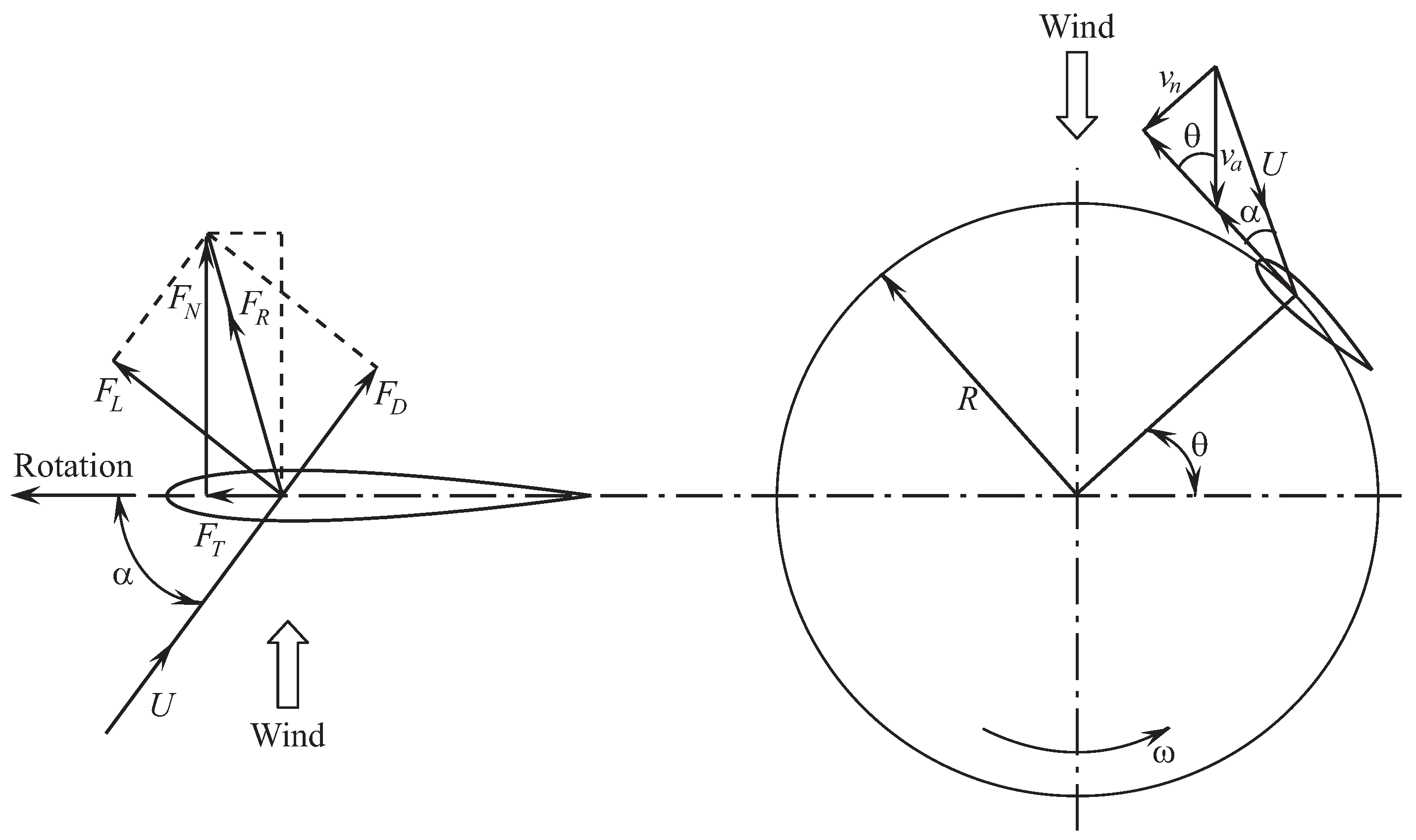

This is easy to remember if you think of the front of the airfoil as leading its movement through the air. The front of the airfoil is named the leading edge and the rear the trailing edge. Before we do this we’ll start by presenting a few fundamental definitions in order to understand how and why an airfoil is shaped as it is. We are now going to move from looking at the wing in planform and concentrate on the section profile of the airfoil that is used on the wing. We also discussed the aspect ratio and how a longer, thinner wing will reduce the total drag of the wing up to a particular speed whereafter transonic speed effects begin to dominate the total drag produced which necessitating a sweeping of the wing to combat the transonic drag rise. In this post we look more closely at the shape of the wing airfoil: why this differs from aircraft to aircraft, and how a careful airfoil selection will help to produce the flying characteristics you desire for your airplane.Īfter reading the post on wing area and aspect ratio, you should appreciate that there exists a very clear relationship between the size (weight) of the aircraft and the size of the wing (wing area) required to operate the aircraft as intended. Specifically we looked at wing area and aspect ratio.

In a previous post we looked at the importance of the shape and plan-form of the wing, and how this has a great impact on the flying characteristics of the aircraft. You can create some pretty advanced equations in solidworks.This is part 5 in a series of fundamental aircraft design articles that aims to give you an introduction to aircraft design principles. It has over 100 equations spreqd between the models and assembly. It does more as well, but too much to explain. It then adds and removes the total number and size of screw based on info entered. I have a baseplate/cover assembly that resizes and inserts all of my needed mounting screw holes entirely based on the user entering the LxWxH in the document properties. Name all of your dimensions names that make sense to you to make the equations easier. So I use 3 construction lines, all dimensioned and labeled as to what they are. One good tool is using dimensioned construction lines as placeholder for variables needed in the equation that do not represent a physical dimension.įor example, I use an equasion to give me the fractional size of a screw from the modeled diameter. Figure out the math you need then start plugging away at equations.

I have some models that use 60+ equations.


 0 kommentar(er)
